Standards review, updated July 29, 2026: Checked against ITU-T L.1397 (10/2025) and ITU-T L.1395 (07/2025). This guide translates the standards into procurement and acceptance-test questions. It does not replace the official text, a project specification or local safety requirements.
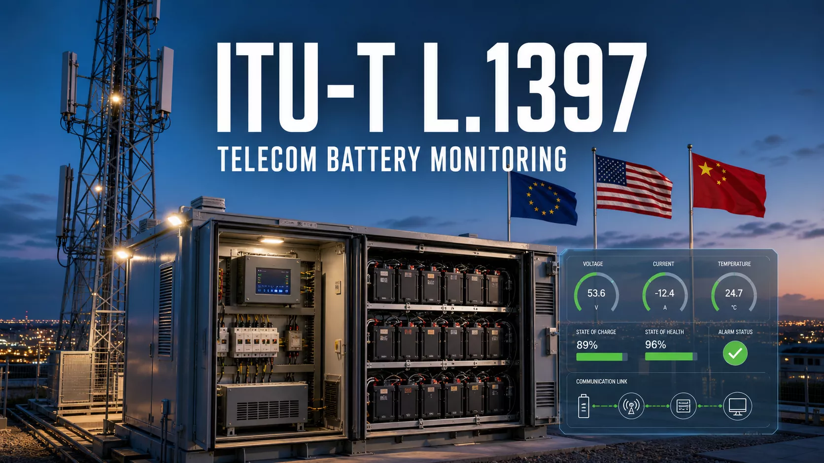
ITU-T L.1397 defines an information model for battery units and battery systems with integrated control and monitoring at telecommunications and data communications sites. In practical terms, it identifies the battery measurements, alarms, events, settings, identification data and control functions that should be available beyond the battery cabinet.
A battery can report 80% state of charge locally while the network operations centre sees nothing because a CAN cable has failed, a gateway has stopped polling or an alarm was mapped incorrectly. The cells may be healthy, yet the operator has lost visibility of the reserve that keeps the site on air.
L.1397 addresses this operational gap. It gives operators, TowerCos, equipment vendors and energy service companies a common basis for discussing what battery information must cross an interface. It does not, by itself, prove that a battery is safe, that its state-of-health calculation is accurate or that two products using different protocols will connect without integration work.
What Does ITU-T L.1397 Actually Cover?
The Recommendation was approved on October 7, 2025 and is currently in force. It was developed jointly by ITU-T Study Group 5 and ETSI Technical Committee Environmental Engineering. ITU-T L.1397 and ETSI ES 202 336-11 V1.2.1 are technically equivalent.
| Item | What it means for a buyer |
|---|---|
| Scope | Battery units and systems with dedicated, integrated control and monitoring for telecom and datacom equipment |
| Architecture | Defines integrated battery units and multi-unit integrated battery systems |
| Information model | Describes the minimum information exchanged at the monitoring and control interface |
| Information types | Alarms, events, live measurements, records, configuration, controls and equipment identity |
| Normative content | Annex A provides the minimum monitored information required by the Recommendation |
| Additional content | Appendix I lists useful non-mandatory functions and data |
| Related generic layer | ITU-T L.1395 defines the wider monitoring architecture, information handling and management concepts |
The official ITU-T L.1397 publication describes its minimum information set in natural-language tables. This matters when evaluating a compliance claim: the standard identifies the information that must be exposed, but a project still needs a machine-readable point map and an agreed transmission method.
Why Telecom Battery Monitoring Is More Than a Dashboard
At an urban site, the battery may carry only a short outage. At a weak-grid or off-grid site, it may cycle daily. ITU-T L.1397 notes that grid-connected standby can range from roughly 10 minutes to 48 hours, while off-grid autonomy can extend for several days. Monitoring must therefore suit both backup and routine energy operation.
Useful monitoring must detect the fault, identify the affected unit and supervise the communication path. A protective trip, low state of charge or excessive temperature is actionable only when the operator can distinguish one failed battery from a system-wide problem.
The last point is often missed in low-cost remote monitoring. No alarm is not the same as no fault. L.1397 specifically notes that an upper network element, such as the remote management application, should detect partial communication failures involving a battery management system or master battery management module.
IBU and IBS: The Two Architectures a Buyer Must Recognize
Integrated battery unit (IBU)
An integrated battery unit combines a battery cell string with a battery management system. A typical nominal IBU voltage is 24 V or 48 V. Its BMS handles protection, voltage-limit detection, charge balancing, alarms and data acquisition. The unit may also include a fuse or breaker, contactor, heater and current regulation.
A single IBU may communicate with an external management application over a data connection such as CAN, and it may also provide a dry-contact alarm. A dry contact is useful as a basic fallback, but it cannot carry the same diagnostic detail as a structured data interface.
Integrated battery system (IBS)
An integrated battery system contains one or more IBUs connected to the DC bus. Several parallel units may nominate one IBU as master, or an optional master battery management module may supervise the group. The MBMM can coordinate safety control, status, alarms, data acquisition and history across the battery system.
| Management level | Typical responsibility | Procurement risk |
|---|---|---|
| Cell string and BMS | Local protection, balancing, measurement and unit status | Important cell data may remain proprietary or inaccessible |
| Master IBU or MBMM | Aggregates multiple units and reports system-level condition | A single communication failure can hide several otherwise working batteries |
| Control unit or data gathering unit | Collects, stores and translates site-equipment data | Polling, scaling or register-map errors can corrupt the NOC view |
| Local or remote management application | Alarm handling, records, remote supervision and intervention workflow | Missing timestamps, severity rules or communication-loss alarms delay response |
| Network management system | Fleet-level visibility, ticketing and operational prioritisation | Over-aggregation can turn a specific battery fault into an unhelpful generic alarm |
This hierarchy matters on shared sites, where batteries, radio equipment and energy services may have different owners. A structured model lets the parties exchange useful facts without giving every user direct BMS access.
The Minimum Data Set in Plain English
Annex A of L.1397 forms an integral part of the Recommendation. Its minimum set goes well beyond voltage and a generic battery alarm. The requirements apply according to the IBU or IBS architecture and the functions fitted to the equipment.
| Information group | Examples in the L.1397 minimum set | Why the buyer needs it |
|---|---|---|
| Protective alarms | Open or tripped protective device, cell overvoltage or undervoltage, battery low voltage, overcurrent, unsafe temperature and safe mode | Shows whether stored energy is physically available to the load |
| Battery-condition alarms | Low or fully discharged SoC, abnormal SoH and battery overcharge | Separates immediate reserve risk from longer-term replacement risk |
| Events | Alarm set and clear, charge/discharge cycle count and changes of operating mode | Provides sequence and context for fault investigation |
| Live measurements | Terminal DC voltage, charge/discharge current and battery temperature | Supports real-time diagnosis and comparison with rectifier and load data |
| Energy and capacity data | Cumulative Wh and Ah charged and discharged, SoC, SoH and remaining capacity | Helps assess cycling duty, reserve and ageing |
| Records | Temperature history and minimum/maximum cell or cell-group temperatures | Reveals thermal stress that a current-value dashboard can miss |
| Configuration and control | Date and time, alarm and test parameters, safe reset, software download and operating-mode settings | Allows controlled maintenance and confirms that thresholds match the approved design |
| Identity | Hardware and software versions, manufacturer, model, serial or part number, cell manufacturing date and design/usable capacity | Supports traceability, firmware control, warranty decisions and fleet analysis |
The minimum table specifies terminal-voltage accuracy of plus or minus 0.1 V and battery-temperature accuracy of plus or minus 2 degrees Celsius. It also calls for five-minute temperature records, limited to a defined number of entries. Its configuration section gives examples of five-minute records for one year and daily minimum, maximum and average values across the design life.
Do not convert those examples into a blanket claim that every L.1397 implementation stores every measurement for the full battery life. Retention, available memory, sampling interval and export format should appear explicitly in the purchase specification.
Optional Does Not Mean Unimportant
Appendix I is non-mandatory, but its branch-current and cell-voltage imbalance, battery replacement, temperature-sensor failure, remaining-autonomy, battery-age and anti-theft information can be valuable at remote sites.
For a single urban cabinet within an hour of a maintenance depot, some optional points may have limited economic value. For an off-grid rural site reached by an all-day drive, estimated autonomy and branch-current imbalance may prevent a failed visit or an avoidable outage. The project risk should decide which optional points become contractual requirements.
For parallel batteries, specify branch-current and cell-voltage imbalance. Solar sites benefit from time-on-charge, remaining autonomy and ageing-adjusted capacity. Hot cabinets justify sensor-failure and thermal-history data, while exposed sites may need anti-theft state. Mixed-chemistry systems need explicit operating mode and approved charging parameters.
What L.1397 Does Not Guarantee
It does not mandate one field protocol
The Recommendation mentions CAN as a common IBU bus and recognises dry contacts, but its information model is not a universal plug. Suppliers may use CAN, Modbus, SNMP, REST or a proprietary gateway with different objects, addresses and scaling.
ITU-T L.1395 provides the wider, protocol-independent management approach and discusses protocol-specific representations. The project must still define the protocol, physical interface, register or object map, units, scaling, update rate and version. See the official ITU-T L.1395 publication for the generic interface layer.
It does not validate SoC or SoH algorithms
SoC and SoH are required information, but a displayed percentage is an estimate produced by the battery’s model. Accuracy depends on chemistry, calibration, temperature, current measurement, ageing history and the manufacturer’s algorithm. A buyer should ask how SoH is defined, what causes recalibration and how the estimate was validated at the relevant duty cycle.
It is not a battery safety certification
L.1397 addresses monitoring and control information. It does not replace product-safety, transport, electromagnetic-compatibility or installation requirements. Depending on the battery and market, a project may separately require evidence against standards or rules such as IEC 62619, UN 38.3, applicable fire codes, low-voltage requirements and local electrical regulations.
It is not a complete cybersecurity specification
The ability to change thresholds, reset defaults or download BMS software is operationally useful and security-sensitive. A standards-aligned point list does not tell the buyer who can issue commands, how credentials are protected, whether firmware is signed or where remote data is stored. Those controls belong in the system and cybersecurity specification.
How to Write L.1397 into an RFP
A weak requirement says, “Battery monitoring shall support ITU-T L.1397.” Suppliers can interpret that sentence in very different ways. A usable requirement identifies the edition, architecture, mandatory and project-selected optional points, protocol mapping, permissions and acceptance evidence.
Suggested procurement wording: The offered integrated battery unit or integrated battery system shall provide the applicable minimum monitoring, event, data, configuration, control and identification information defined in ITU-T L.1397 (10/2025), Annex A. The supplier shall identify any non-applicable point with a technical reason. The selected Appendix I points listed in the project schedule shall also be provided. Before FAT, the supplier shall submit a complete protocol and point-mapping document showing object or register identifiers, data type, unit, scale, valid range, update interval, alarm set/clear logic, severity, access permission and behaviour when data is unavailable.
Add these project decisions rather than leaving them to commissioning:
- State whether each battery module is an IBU and whether the system uses a master IBU or MBMM.
- Name the required standard edition: ITU-T L.1397 (10/2025), not simply “latest”.
- Attach a compliance matrix covering every applicable Annex A row.
- Select the Appendix I items justified by site access, cycling duty and outage cost.
- Define the field bus and upstream protocol, connector, pinout and termination.
- Specify units, signed values, scaling, byte order, time base and unavailable-data code.
- Set data refresh, event latency, record interval and retention period.
- Separate read-only and control accounts, and list every remotely writable point.
- Define data ownership, bulk export and operation without a supplier cloud.
- Require the NMS to distinguish an equipment alarm from stale or lost communications.
- Record approved firmware, rollback and local service procedures.
Evidence Behind a Supplier’s Compliance Claim
| Evidence level | What the supplier provides | Buyer’s interpretation |
|---|---|---|
| Marketing statement | “Supports ITU-T L.1397” | Not enough for technical approval |
| Compliance matrix | Each Annex A item marked compliant, not applicable or exception | Useful first review, but still self-declared |
| Interface specification | Protocol map, data definitions, alarms, controls and versions | Shows whether integration is technically possible |
| Laboratory record | Measured values and injected faults compared with reported data | Demonstrates behaviour under controlled conditions |
| Witnessed FAT | Buyer observes normal operation, faults, link loss, restart and data export | Strong project-specific evidence |
| SAT and NOC proof | End-to-end alarm and control tests after installation | Confirms the complete path, not only the battery |
A battery BMS may be correct while a third-party gateway maps one register incorrectly. A polished portal may also hide limited cell data. Acceptance must cover the chain from the battery sensor to the operator’s screen.
A Practical FAT and SAT Test Schedule
The test does not need to damage a battery. Many conditions can be simulated through approved BMS test functions, signal injection, configurable thresholds or controlled disconnection. The supplier should define the safe method before the test begins.
| Test | Action | Evidence to record |
|---|---|---|
| Voltage and current comparison | Compare BMS, calibrated instrument, gateway and NMS readings at stable and changing load | Value, unit, scale, timestamp and allowed deviation at each layer |
| Temperature alarm | Use an approved simulator or temporarily lower the test threshold | Alarm set time, severity, source identity, message and clear time |
| Low SoC condition | Use a controlled discharge or vendor test mode | Threshold, delay, reported SoC and downstream ticket creation |
| Protective-device state | Operate the designated breaker or use its test input | Correct unit identification and unambiguous open/tripped state |
| Operating-mode change | Move between approved charge, discharge or idle states | Event sequence without false critical alarms |
| IBU communication loss | Disconnect one approved data link while the DC system remains safe | Specific lost-unit alarm and stale-data indication |
| MBMM-to-gateway loss | Interrupt the upstream field bus | Communication alarm generated above the failed link |
| Restart and recovery | Restart the monitoring controller under an approved procedure | Safe defaults, restored settings, time synchronisation and event record |
| History export | Export temperature, energy and alarm records | Open documented format, complete time range and consistent identifiers |
| Unauthorised control attempt | Use a read-only account to request a protected command | Command rejected and security event logged |
For SAT, repeat at least the communication-loss, alarm-routing, timestamp and local-access tests through the installed network. A successful factory test proves the product configuration used at FAT. It does not prove that firewall rules, site gateways and NMS mappings are correct after deployment.
Worked Example: Four 48 V Battery Units at a Hybrid Cell Site
Consider a site with four parallel 48 V lithium battery units, a DC power system, photovoltaic input and generator backup. Each battery is an IBU with its own BMS. An MBMM supervises the four units, a site controller collects power and environmental data, and the NOC receives alarms over the operator’s private network.
At 14:10, IBU 3 stops sharing discharge current. Bus voltage remains normal because the other units carry the load, so a voltage-only monitor may look healthy. A stronger specification can expose three facts:
- IBU 3 branch current is abnormal or unavailable.
- The IBS still reports total voltage, current, SoC and operating mode.
- The NOC receives a unit-specific event or communication alarm with a timestamp.
The operator can decide whether the reduced reserve requires an urgent visit. Without unit identity and communication health, the condition may remain hidden until a long outage.
Now consider a different fault: the cable between the MBMM and site controller is unplugged. The MBMM cannot report an alarm through a link that no longer exists. The controller or remote application must recognise that expected data has become stale. This is why a communication watchdog, polling timeout and “unknown” state belong in the acceptance test.
Cybersecurity and Data Ownership Questions
Battery monitoring is normally less sensitive than subscriber traffic, but it still reveals site location, reserve condition, power failures and maintenance activity. Remote control can also affect availability. A compromised account that changes a low-voltage threshold or pushes unapproved BMS firmware creates a physical operational risk.
Ask the supplier to document:
- Which interfaces are enabled by default and which can be disabled.
- Whether unique credentials are required per site or device.
- How read-only monitoring is separated from configuration and firmware privileges.
- How communications are authenticated and encrypted above the field bus.
- How firmware is signed, verified, rolled back and logged.
- Where cloud data is stored, who can access it and how long it is retained.
- Whether local operation and record export continue without the supplier cloud.
- How vulnerabilities and end-of-support dates are communicated.
How L.1397 Changes Supplier Evaluation
The Recommendation gives suppliers a common target when batteries, rectifiers, solar controllers and NMS software come from different manufacturers. It does not eliminate supplier qualification.
For telecom energy vendors, the useful engineering work is to provide an open point map, demonstrate alarm behaviour and preserve local operation when the WAN fails. Buyers comparing integrated solar, battery and DC power architectures can review practical telecom power systems and engineering services from Huijue Group. The product page is a starting point for system scope, not evidence that a quoted battery model complies with L.1397; that evidence should be requested for the exact hardware, BMS firmware, gateway and project configuration.
Ask every bidder for the same proof. A brand name does not replace a point-level matrix, and a different dashboard is not a technical failure. The required data must remain accurate, available, controlled and supportable throughout system life.
Common Buyer Questions
Is ITU-T L.1397 mandatory for every telecom battery?
No. It becomes contractual when adopted into a regulation, operator standard or purchase specification. Cite the edition and required evidence in the RFP.
Does L.1397 require CAN, Modbus or SNMP?
It does not impose a single universal field protocol. CAN is given as a common example for IBU communication. The project must state the actual protocol and data mapping required at each interface.
Can the Recommendation be used with lead-acid batteries?
Its scope is integrated monitoring rather than one chemistry, and the text includes lead-acid and hybrid concepts. An unmonitored conventional string needs a control or data-gathering layer to expose the required information.
Does an L.1397 claim prove cell-level monitoring?
No. The minimum set includes cell-condition alarms and cell or cell-group temperature records. If every cell voltage and temperature must be live, state that separately.
The One Question to Put in the Next Battery Meeting
Do not ask only, “Can your BMS show SoC?” Ask: When one battery unit or one data link fails, exactly what will our operator see, how quickly will it appear, and what evidence proves that behaviour before shipment?