The WDF-C12 is documented as a fully enclosed, framed network cabinet for indoor communications and IT equipment. Its enclosure can create a clear physical boundary around devices and cabling, but that boundary also changes how technicians reach equipment and how heat leaves the cabinet. The design task is therefore not simply to choose a U height. It is to plan access, airflow, cable movement and loading before the enclosure is fixed to a wall or floor.
The supplied technical sheet covers 4U to 18U cabinets, all 600 mm wide, with 450 mm and 600 mm depth choices. It also lists solid, perforated and glass front-door configurations, top and bottom cable routes, wall-mounted and floor-standing installation, and a family static-load range of 60 to 100 kg.
Those specifications define the available envelope. They do not decide how the cabinet should be used. A reliable design starts with the work technicians must perform after the cabinet is installed.
Think of the cabinet as an equipment boundary
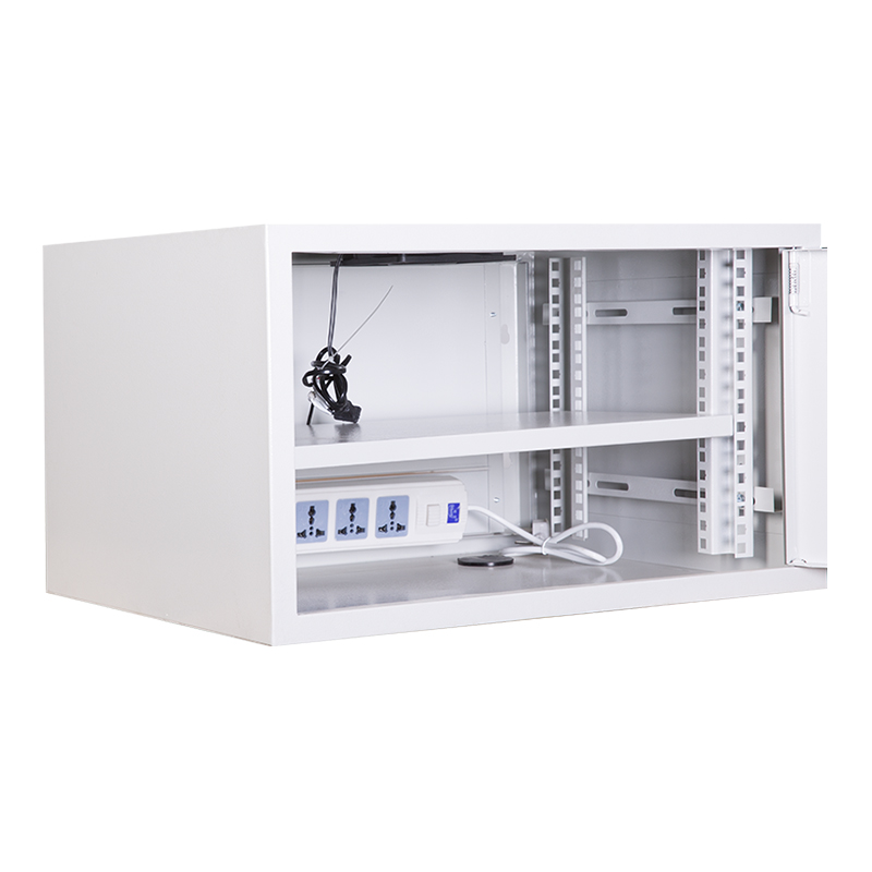
An open frame mainly provides mounting structure. An enclosed cabinet adds panels and a door between the equipment and its surroundings. This can improve organization, limit casual contact, hide cable congestion and provide a defined mounting environment for accessories. It can also make the installation easier to manage visually in offices, communication rooms and customer-facing technical areas.
The same boundary can create constraints. A closed door may restrict inlet air. Fixed side construction can make rear connectors difficult to reach. A wall directly behind the cabinet may eliminate rear service access. Cable bundles entering through one opening can block equipment removal. None of these problems is visible in a model number.
Before approving an enclosed cabinet, answer four questions:
- Which equipment must be reached during normal maintenance?
- Where does cooling air enter and leave?
- How will cables move when equipment or a door is serviced?
- Can the loaded enclosure be supported safely at the selected location?
Plan the service path before the mounting position
Many compact-cabinet problems begin when the installer chooses a convenient wall position before checking the service path. A door may open into a corner. A ceiling tray may force cables across the top ventilation area. A neighboring cabinet may block side access. A technician may be able to see a failed switch but not remove its power connector.
Start with the equipment-maintenance sequence instead:
-
- Open the front door through the required angle.
- Reach every device that needs routine inspection.
- Release mounting screws, rails or shelf fasteners.
- Disconnect power and data without pulling adjacent cables.
- Support and remove the device safely.
- Reinstall it without trapping cables or disturbing grounding connections.
The WDF-C12 sheet identifies a fully enclosed frame but does not explicitly describe quick-removal side panels. Side access should therefore be treated as unconfirmed until the controlled drawing shows the panel construction and removal clearance. If a project depends on side servicing, include that requirement in the RFQ rather than assuming it from a product photograph.
Choose a door by thermal behavior and inspection needs
The source document lists three modular front-door types. Each creates a different relationship between the cabinet interior and the room.
| Door type | Useful when | Check before approval |
|---|---|---|
| Perforated steel | Active equipment needs direct room-air exchange | Open area, equipment airflow direction, dust conditions and noise |
| Glass | Status lights or displays need visual inspection through a closed door | Heat rejection, fan requirement, glare, lock and glass specification |
| Solid steel | An opaque physical barrier and clean exterior are preferred | Alternative air openings, forced ventilation and allowable internal temperature |
A glass or solid door does not automatically make a cabinet unsuitable for active equipment. It does mean that ventilation must be provided elsewhere and verified against the actual heat load. A fan module can assist air movement, but it cannot compensate for an obstructed path or replace room-level cooling.
Build the airflow path around installed devices
Cooling performance is determined by the complete path from room air to equipment inlet and from equipment exhaust back to the room. Inside a compact enclosure, shelves, cable bundles and unused spaces can redirect that path.
Use the equipment list to map:
- Inlet and exhaust faces for every active device
- Total heat output under expected operating load
- Clear space required in front of and behind each device
- Areas where cable bundles could block ventilation
- Fan location, airflow direction, power and replacement access
- Room temperature at the proposed cabinet position
Do not rely on the cabinet’s external volume as evidence of adequate cooling. A deeper enclosure may provide more space, but it may also allow hot air to recirculate if inlet and exhaust zones are not controlled. Temperature measurement during commissioning is more useful than an assumption based on door style.
Use cabinet depth to protect the service zone
The WDF-C12 family is documented with 450 mm and 600 mm external depth options. Instead of treating depth as a product-size comparison, use it to protect three separate zones:
- Equipment zone: the chassis, mounting ears, shelf or rails.
- Connection zone: power plugs, network connectors, fiber adapters and cable bends.
- Service zone: the hand and tool clearance needed to disconnect and replace equipment.
A device that physically fits in the first zone may still fail the installation test if the other two disappear when the door closes. Use a drawing that shows the internal rail position, usable depth and door clearance. For devices with rear connectors, include the connector body and the manufacturer’s minimum bend radius in the depth calculation.
Keep cable entry separate from cable management
The documented top and bottom cable channels provide alternative entry directions. They do not organize the cables after they enter. That requires a routing plan.
Separate power, copper data, fiber and grounding conductors as the project requires. Leave enough slack for termination and planned equipment movement without creating loops that obstruct airflow. Protect cables where they pass through sheet-metal openings, and keep the bundle clear of hinges, locks and fan blades.
The source lists cable managers as an optional configuration. Select their position only after the port layout is known. A horizontal manager can consume rack space; a side route can reduce usable width; a rear bundle can take away connector clearance. Cable-management hardware should appear on the same layout as the installed equipment.
Decide between wall and floor installation from the loaded condition
The WDF-C12 sheet presents both wall-mounted and floor-standing arrangements. The cabinet’s family static-load statement is 60 to 100 kg, but a wall installation cannot be approved from that number alone.
For wall mounting
Calculate the full installed mass, including the cabinet, devices, UPS equipment, shelves, fan modules, power accessories and cables. Cabinet depth moves the center of gravity away from the wall and increases the load on brackets and anchors. The wall material, fixing pattern and installation workmanship are part of the support system.
For floor standing
Define whether the cabinet uses support posts, leveling feet, a base or casters. Casters make an empty cabinet easier to position but change stability and do not eliminate the need for restraint. Confirm the final working height, anti-tip approach and whether cables can tolerate movement.
For both methods, the selected model’s rated load and load distribution must be confirmed in the approved drawing and quotation.
Treat accessories as parts of the operating system
The source ordering guide identifies L-rails, fixed shelves, a fan module, cable-management hardware, a busbar, casters and support posts as configurable items. These are not decorative extras.
- L-rails can provide rear or side support for compatible equipment.
- Fixed shelves support devices without rack-mounting ears, subject to depth and load.
- Fan modules add forced airflow and require a defined intake, exhaust and power connection.
- Cable managers control routing and bend radius but consume installation space.
- Busbar or grounding hardware must be defined by function, conductor size and bonding plan.
- Casters and support posts affect movement, leveling, stability and final height.
List every required accessory in the BOM. A cabinet ordered by external dimensions alone can arrive without the support, ventilation or cable-management components needed to operate it.
Use the source dimensions as planning boundaries
The WDF-C12 ordering sheet provides the following external size framework:
| Rack height | Cabinet width | Available depths | Listed overall height |
|---|---|---|---|
| 4U | 600 mm | 450 or 600 mm | 274 mm |
| 6U | 600 mm | 450 or 600 mm | 363 mm |
| 9U | 600 mm | 450 or 600 mm | 496 mm |
| 12U | 600 mm | 450 or 600 mm | 629 mm |
| 15U | 600 mm | 450 or 600 mm | 762 mm |
| 18U | 600 mm | 450 or 600 mm | 892 mm |
These values help reserve wall or floor space. They do not state the usable internal volume, mounting-rail adjustment range or clearance behind a closed door. Obtain the controlled dimension drawing before releasing the room layout.
Commission the enclosure as an installed assembly
A final check should test the cabinet in the condition in which it will operate, not only as an empty enclosure.
- Confirm cabinet position, level, anchoring and stability.
- Verify equipment mounting and shelf or rail support.
- Open and close the door without contacting cables or equipment.
- Confirm locks, hinges and required access control.
- Inspect grounding and bonding connections.
- Check cable protection, labeling and bend radius.
- Verify fan direction and ensure all airflow openings are clear.
- Measure operating temperature at representative equipment inlets.
- Record the installed load and keep the approved drawing and BOM.
The source document lists IP20 and reference operating conditions of -5°C to 55°C, relative humidity no greater than 80% at 30°C and atmospheric pressure from 65 to 110 kPa. Installed electronics may have narrower environmental limits. The cabinet is an indoor enclosure and should not be treated as protection against rain, condensation, corrosive atmosphere or uncontrolled dust.
Confirm current compliance rather than repeating legacy references
The supplied sheet cites several rack-dimension, enclosure, vibration and grounding standards. Some references use older designations. A current project should identify the applicable standard, product revision, tested configuration and available evidence instead of presenting the historical list as a blanket certification.
If compliance documents are required, state the destination country and required report or certificate in the RFQ. Confirm whether each statement describes dimensional compatibility, a design requirement or a completed test on the quoted model.
Questions to answer before requesting a quotation
- Which devices will be installed, and how deep are they with connectors?
- Which devices need routine front, rear or side service?
- What is the total occupied U space, including accessories?
- How much heat will the installed equipment release?
- Which door supports the required airflow and inspection method?
- Will cables enter from above, below or both?
- What is the full installed weight and center-of-gravity condition?
- What wall, floor, anchor or mobility arrangement is required?
- Which shelves, rails, fans, cable managers and grounding parts are needed?
- Which drawings, tests, labels and acceptance records must accompany the order?
Current project buyers can compare the documented HJWA single-section wall-mount cabinet, HJWB swing-out wall-mount cabinet and HJCC floor-standing network cabinet. The closest current platform depends on the required access method, depth, loading and installation location.
Frequently asked questions
What makes the WDF-C12 an enclosed network cabinet?
The supplied technical sheet describes an integral enclosed framed structure with a modular front door and top and bottom cable channels. The final panel and access arrangement should be confirmed on the controlled drawing.
Does an enclosed cabinet provide better cooling?
Not automatically. An enclosure can help define an airflow path, but doors, cables, shelves and fans must be arranged around the equipment’s inlet and exhaust directions. Cooling should be verified under operating load.
Can a glass door be used with network switches?
It may be suitable when the heat load and ventilation plan allow it. Confirm device airflow, cabinet openings, fan requirements and expected internal temperature before selecting the door.
Can technicians service equipment from the side?
Do not assume so. The source sheet does not explicitly confirm quick-removal side panels. If side access is required, place it in the RFQ and verify the panel construction and removal clearance on the drawing.
Is 600 mm depth always better than 450 mm?
No. Additional depth can improve connector and cable clearance, but it increases wall projection and changes the center of gravity. Choose the smallest approved depth that preserves the equipment, connection and service zones.
Does the 60-100 kg load statement apply to every installation?
No. It is a family-level statement in the supplied sheet. The selected model, wall or floor mounting method, shelf loads and load distribution must be confirmed for the project.
Is the WDF-C12 suitable outdoors?
No. The document lists IP20 and describes an indoor network cabinet. Outdoor or harsh-environment installations require a different enclosure and environmental review.
Design for the maintenance visit that happens later
The value of an enclosed network cabinet becomes clear after installation, when equipment needs to be inspected, disconnected or replaced. A good layout keeps the equipment protected without turning routine service into a cable-removal project.
Send the equipment schedule, service-access requirements, airflow data, mounting location, cable-entry plan, installed load, accessories, quantity and destination through the rack cabinet quotation form. Huijue can review the requirement against the current server rack and network cabinet portfolio and define the proposed model, drawing and BOM.
Evidence note: Product construction, size boundaries, options and environmental references in this article follow the supplied WDF-C12 technical document. Current availability, side-panel design, usable internal dimensions, materials, load limits, standards, tests and included accessories must be confirmed in the latest controlled commercial documents.